EN
EN
 it
it  fr
fr  de
de  ru
ru  pt
pt  es
es
Get in Touch with WeiYuanDa Now!


Quick Answer: Aluminum PCB thermal performance is not determined by the aluminum plate alone. In most designs, the thermal dielectric between the copper circuit and the metal base is the main bottleneck, while copper area, dielectric thickness, component layout, interface material, and the external heat sink complete the heat path.
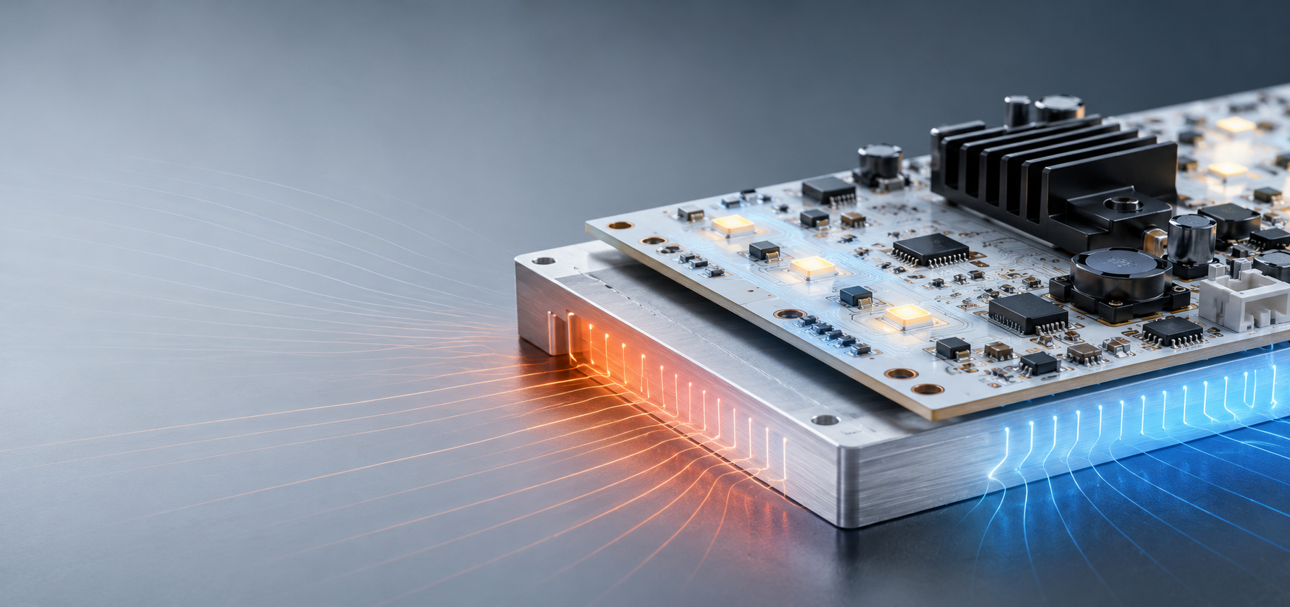
Engineers often compare aluminum boards by a single conductivity number, but that number can be misleading when it is separated from the actual stack-up. A board with a higher-rated dielectric can still run hotter if the dielectric is thick, the copper spreading area is limited, the component pad is poorly connected to the heat path, or the board-to-heat-sink interface is weak.
This guide explains how to interpret aluminum PCB thermal conductivity, how heat moves through a metal-core board, and what information an OEM should provide before a prototype is released.
Thermal conductivity describes how readily a material conducts heat and is normally expressed in W/m·K. In an aluminum PCB, however, several materials are arranged in series, so the conductivity of one layer does not equal the thermal performance of the complete board.
The aluminum base is highly conductive compared with an organic laminate, but heat generated by an LED, MOSFET, rectifier, or power IC must first leave the component pad, spread through the copper, cross the thermal dielectric, enter the aluminum core, and then move into a heat sink, enclosure, or surrounding air. The layer with the highest thermal resistance can dominate the temperature rise.
A more useful engineering question is therefore not only “What is the conductivity?” but “What is the total thermal resistance from the component junction to the final cooling surface?”
The heat path of a typical single-layer metal-core PCB is component junction → solder joint → copper circuit → thermal dielectric → aluminum base → thermal interface material → heat sink or enclosure.
The standard structure used in a professional aluminum PCB includes a copper circuit layer, a thermally conductive insulation layer, and an aluminum base. The copper layer spreads heat laterally, the thermal dielectric provides electrical isolation while allowing heat transfer, and the aluminum core distributes heat across a wider area.
For LED modules, the board is only one part of the system. The mechanical contact between the board and luminaire body, screw pressure, surface flatness, thermal grease or pad thickness, and airflow all influence the final junction temperature. WYD’s aluminum PCB product page provides a useful starting point for reviewing available structures and manufacturing options.
The following variables should be evaluated together because changing one parameter can shift the thermal bottleneck to another part of the assembly.
Parameter | Why It Matters | What to Confirm Before Quotation |
Dielectric thermal conductivity | A higher-conductivity insulation layer can reduce through-thickness resistance, but only when the value is verified for the selected material grade. | Material name, tested value, thickness, voltage isolation requirement |
Dielectric thickness | Thermal resistance generally increases as the insulation layer becomes thicker. | Minimum safe thickness for dielectric strength and process capability |
Copper thickness and copper area | Copper spreads heat laterally and supports current, but adding copper does not automatically solve a poor vertical heat path. | Copper weight, pad size, plane area, local neck-downs |
Aluminum core thickness | A thicker core improves stiffness and heat spreading over a larger area, but it adds weight and does not remove dielectric resistance. | Board dimensions, mounting method, flatness and depaneling needs |
Board-to-sink interface | Air gaps, uneven pressure, rough surfaces, or an overly thick pad can create substantial interface resistance. | TIM type, mounting pressure, heat-sink flatness, enclosure material |
LED lighting usually requires stable temperature distribution across many light sources, while power electronics often concentrates heat around a smaller number of high-loss components.
In a lighting module, engineers should review LED spacing, copper spreading, lumen maintenance targets, ambient temperature, luminaire housing, and whether the board is continuously driven near maximum power. The WYD lighting PCB solutions page shows how an LED lighting aluminum PCB can be integrated into a broader thermal design rather than treated as an isolated part.
In power supplies, motor drivers, converters, and inverter modules, the design must also account for high current, switching losses, creepage and clearance, local copper density, and heat generated by magnetic components or semiconductors. For these projects, the energy and power supply PCB solution should be reviewed together with the board stack-up.
A reliable RFQ defines the thermal objective, electrical isolation requirement, mechanical constraints, and test method instead of requesting only a generic conductivity value.
Provide the component power map or at least the maximum dissipation of the hottest devices. Include board size, copper weight, layer count, dielectric thickness preference, minimum isolation voltage, aluminum thickness, surface finish, solder mask color, mounting hole locations, and the expected heat-sink interface.
It is also useful to state the maximum ambient temperature, allowed component or board temperature, cooling method, operating duty cycle, and whether the product will be validated by thermocouple, infrared imaging, or junction-temperature estimation.
· Define the heat source: component type, quantity, power loss, pad geometry and operating duty cycle.
· Define the cooling boundary: natural convection, forced air, enclosure conduction, cold plate or external heat sink.
· Define electrical isolation: working voltage, surge requirement, creepage and clearance targets.
· Define mechanical limits: board thickness, flatness, mounting pressure, outline tolerance and vibration.
· Request a documented stack-up and material grade rather than a generic “high thermal” description.
· Validate the assembled thermal path on a prototype under worst-case ambient and load.
The most common mistake is comparing the bulk conductivity of aluminum with the conductivity of the complete PCB stack-up. Another is selecting the thinnest dielectric without checking dielectric strength, process margin, surface topography, and long-term reliability.
Engineers should also avoid assuming that a thicker aluminum core always lowers the hottest component temperature. When the thermal dielectric or interface material dominates, increasing core thickness may add cost and weight with limited benefit. Likewise, a large heat sink cannot compensate for a poor solder pad, narrow copper connection, or trapped air at the mounting interface.
A capable aluminum PCB manufacturer should review the Gerber data, stack-up, component power information, and mechanical assembly together. WYD PCB can support prototype comparison of dielectric and core options before a production stack-up is frozen.
Not automatically. The value must be considered with dielectric thickness, copper spreading, component layout, board-to-heat-sink contact, and the system cooling method. A balanced stack-up can outperform a higher-rated material used in a weak assembly.
Thermal conductivity is a material property. Thermal resistance describes the temperature rise caused by a particular heat flow through a layer or complete assembly, so it includes material conductivity, thickness, area, and interfaces.
It can improve lateral heat spreading and mechanical stiffness, especially on large boards, but it may have little effect when the dielectric or external interface is the main bottleneck.
Provide power dissipation, board area, target temperature rise, isolation voltage, copper pattern, ambient temperature, cooling method, and mechanical constraints. The material grade and thickness can then be selected together.
Sometimes the metal core and enclosure provide enough cooling for moderate power density, but high-power assemblies usually still require a defined path into a heat sink, housing, or cold plate.
Test a fully assembled prototype at worst-case input voltage, load, ambient temperature, and airflow. Measure critical component and board temperatures after thermal equilibrium and compare them with design limits.